
Case Study: Location Of Generator Pd Sources Using Multiple Sensors
Generator health is one of the single most critical elements of a power-producing operation's ability to maintain a reliable revenue stream. These generators typically operate at medium voltage levels; thus, a high percentage of overall failures are attributed to insulation defects, as is often the case in any medium voltage equipment.
Statistics from IEEE and EPRI studies indicate that approximately 37% of generator failures can be attributed to stator insulation failure. Stator insulation deterioration can be tracked by regular partial discharge (PD) testing or continuous monitoring methods. The importance of monitoring the generator's insulation for PD activity — along with monitoring other common mode failure components such as bearing condition — is a widely accepted practice in North America. This article will briefly address the general application of multiple generator partial discharge sensors and then discuss a recent event where the sensors predicted an impending failure.
Sensor Application
Permanent coupling capacitor sensors can be used to detect generator discharges by connecting a sensor to each bus phase at an accessible location near the generator. The coupling capacitors provide a means of obtaining consistent and calibrated signals. At least one generator monitor manufacturer also uses the generator's existing RTDs to detect PD.
Although the RTDs cannot always provide a calibrated signal, they can be useful for detecting PD deeper in the generator windings, as much as 60-70%, whereas the coupling capacitor typically can only see the first 15% of the windings (Figure 1).
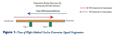

Since the ISO-phase bus can also discharge, an additional set of coupling capacitors should be placed on the bus further away from the first set of sensors to detect the direction of the arriving PD pulses via the time-of-flight method (Figure 2).
A more convenient and cost effective method is to use a set of high frequency CT sensors on the ISO phase ground straps to determine source origination (Figure 3).

Studying individual PD pulse characteristics such as frequency and polarity may assist in determining the likely physical discharge location and the type of discharge occurring.
Case Study
A customer operating a large steam generator experienced a sudden high increase in Phase A PD magnitude discharge (Figure 4).

The high-frequency characteristics of the pulse indicated that the discharge was occurring near the sensors, and the ringing characteristics indicated a surface or interface discharge (Figure 5).
The polarity indicated that the PD source was originating from the ISO phase bus (Figure 6).

The diagnosis: early stages of surface tracking of Phase A ISO Phase insulator located near the vicinity of the PD couplers.
The engineering department planned an immediate outage, and the inspection revealed excessive moisture occurring in Phase A ISO Phase bus (Figures 7, 8, and 9), resulting in early stage surface insulator tracking. This was precisely the same conclusion as diagnosed by the analysis of the PD pulses. Simple repairs were conducted during the outage, and the generator was brought back on line, thereby averting a potential catastrophic failure.


Conclusion
Generator PD monitoring allows tracking of the insulation condition and can provide an early warning of impending failure, thus positively impacting reliability.